
Streetlight & Electrical Asset Monitoring
Follow circuit-current trends. Flag configured abnormal conditions and give maintenance teams a record to investigate.
Discuss your requirementOn-site deployment / live monitoring
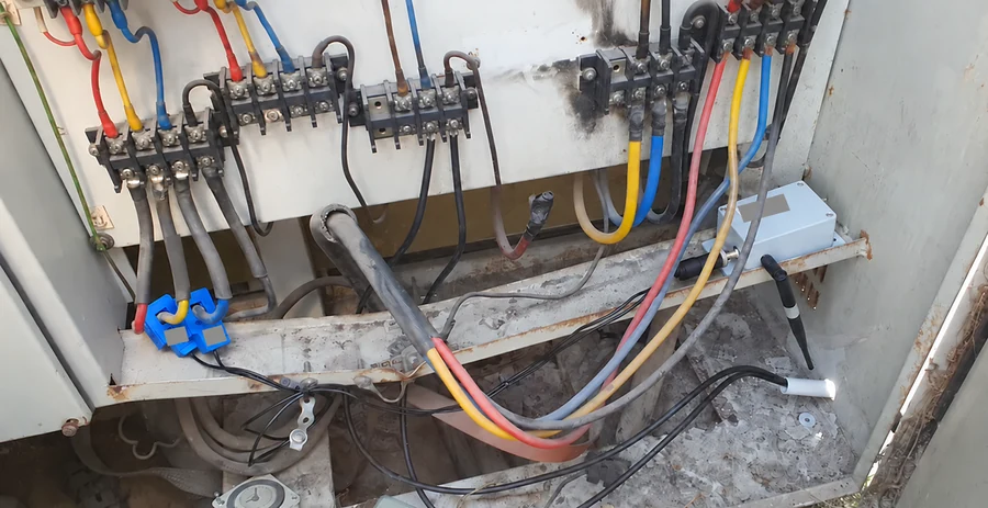
Operational challenge
A patrol sees the condition now. Current history helps show when it changed, against the circuit’s normal schedule and load.
What we monitor
Current condition
Clamp-type measurements on the monitored circuit or phases.
Power-loss indication
A configured change from the expected operating condition.
Overload indication
Current exceeding an agreed threshold.
Unusual consumption
Changes reviewed against the expected circuit pattern.
Trend and event history
Records to support investigation and maintenance decisions.
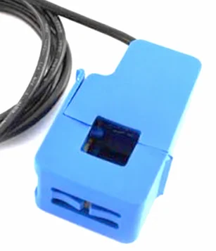
See how the sensing fits
A clamp-type sensor measures current at the selected circuit. The sensor and monitoring hub support current trends, device health and configured alerts.
How the system works
Field sensing
Measure current with clamp-type sensors.
Wireless reporting
Transmit readings through the monitoring hub.
Monitoring platform
Review live trends and historical records.
Alert & response
Flag configured abnormal conditions.
Operational verification
Investigate the circuit and confirm the cause.
Field validation
On-site deployment / live monitoring- On-site installation: Photographs show feeder sensors and the monitoring hub.
- Live records: Dashboard evidence shows current and power conditions.
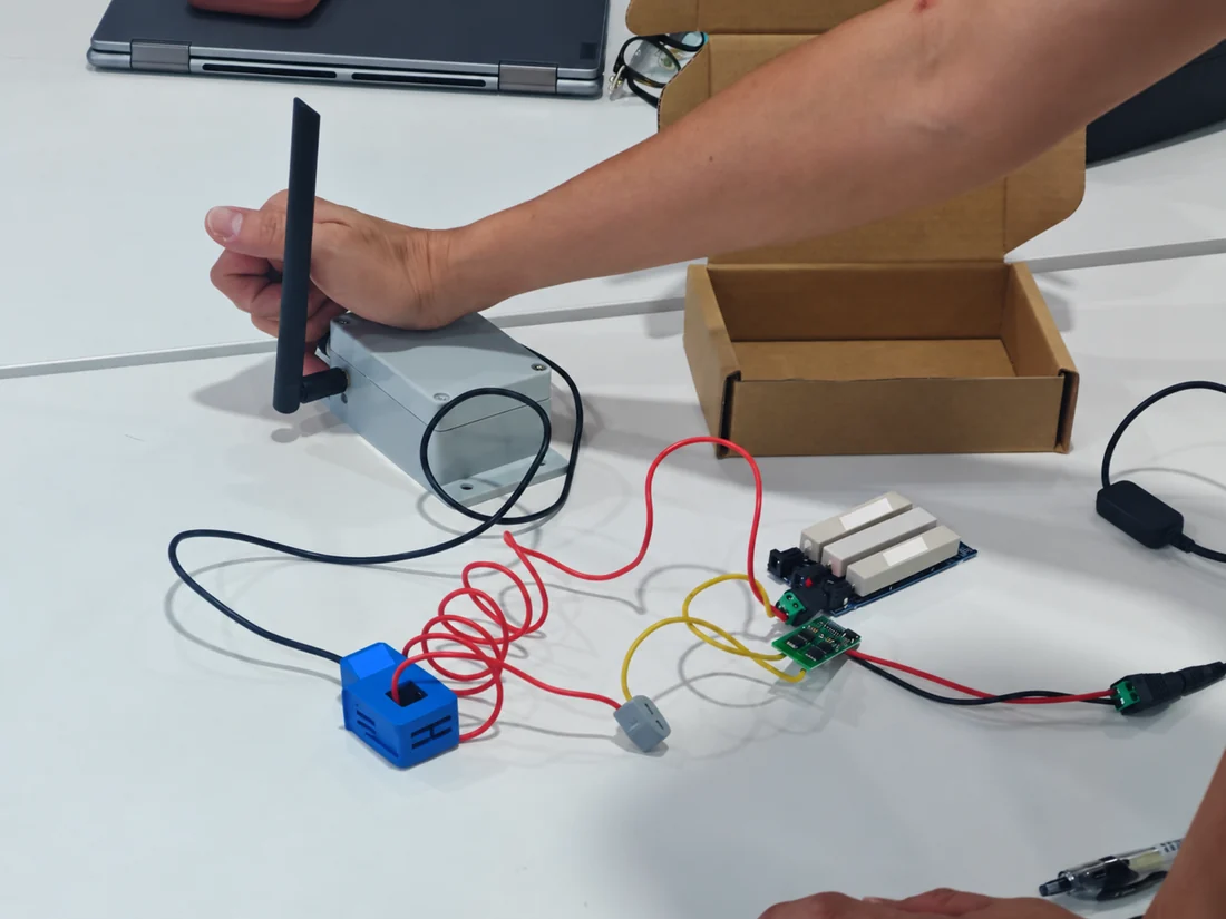
- Bench demonstration: Supplied photographs show clamp sensing, test loads and wireless hardware.
The evidence supports on-site deployment and live monitoring. Outage-prevention rates, savings and long-term diagnostic performance have not been established.
Engineering and reliability considerations
Baseline normal operation
Switching and load changes affect readings; use the expected circuit pattern.
Investigate the cause
A current change is an operational signal, not a confirmed diagnosis.
Agree thresholds and response
Match alert conditions to the circuit and maintenance procedure.
Technical highlights
Review the documented configuration and its deployment limits.
View specifications and configuration notes
- Non-intrusive clamp-type current sensing.
- Three-phase monitoring where applicable to the installation.
- Documented 20 A sensing range, with a 100 A option.
- Configurable alert thresholds and dashboard trend history.
- Wireless mobile-network reporting from the monitoring hub.
- Documented compact configuration with a replaceable battery and IP65 enclosure specification.
The sensing range and final configuration should be matched to the circuit during pilot planning.
Deployment process
Survey & install
Match the feeder and sensing range.
Register & baseline
Record phases and operating periods.
Controlled test
Check agreed load changes.
Tune & verify
Confirm thresholds and alert delivery.
Report & scale
Review evidence before adding circuits.
Discuss Your Monitoring Requirement
Tell us the electrical asset, circuit arrangement and abnormal condition you need to detect. We can propose a practical pilot configuration.
Email AI-REKA