
Road Barrier & Work Zone Monitoring
See barrier position and abnormal tilt. Alert the field team and retain the restoration record.
Discuss your requirementControlled field / prototype testing
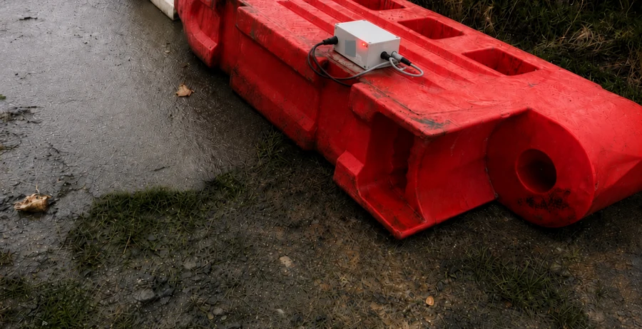
Operational challenge
A barrier can shift between inspections. Teams need its position, event state and confirmation that it has been restored.
What we monitor
Asset position
Location information presented in the monitoring interface.
Tilt / angle
Abnormal position relative to the configured condition.
Movement and overturning
Position and orientation changes relevant to the asset.
Device health
Battery voltage and communication readings.
Event and restoration history
Alarm and alarm-clear records for review.
How the system works
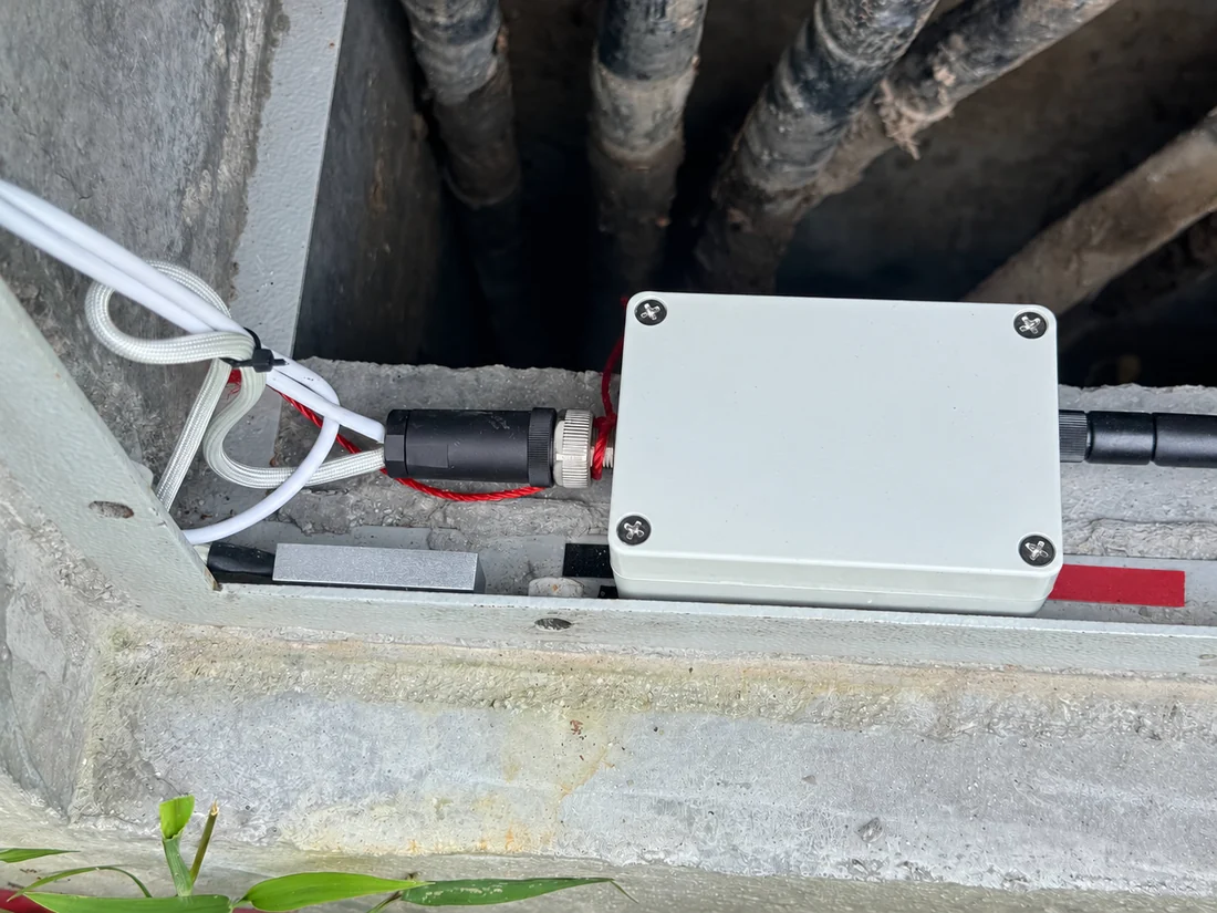
Field sensing
Measure barrier position, angle and device health.
Wireless reporting
Send readings through wireless connectivity.
Monitoring platform
Compare angle with the configured condition.
Alert & response
Send the event and navigation link.
Operational verification
Record clearance after restoration.
Field validation
Controlled field / prototype testing- Working prototype: Position, tilt, dashboard records and mobile notifications demonstrated.
- 30° test condition: A recorded controlled test, not a universal operating threshold.
- Alarm → clear: Event and restoration lifecycle captured.
Evidence remains controlled field / prototype testing. A site pilot must confirm mounting, thresholds and response; fleet rollout and long-term highway performance are not established.
Normal position
Monitor the agreed baseline.
Tilt event
Record the event and notify the team.
Restored position
Record the clear state after restoration.
Illustrative event sequence; not a live measurement or additional field-test result. The recorded 30° condition belongs to the documented prototype test.
Engineering and reliability considerations
Define meaningful tilt
Match the threshold to the barrier design and field requirement.
Check positioning
Confirm location quality and show unavailable position information.
Test restoration
Verify both the alert and the subsequent alarm-clear record.
Review the response
Check event delivery, location guidance and retained history together.
Technical highlights
Review the documented configuration and its deployment limits.
View specifications and configuration notes
- Position tracking and three-axis tilt/angle sensing.
- Configurable abnormal-position threshold.
- Wireless mobile-network reporting.
- Dashboard visibility for voltage, signal, angle and historical records.
- Mobile alert with incident information and a navigation link.
- Hardware configuration and mounting to be confirmed for the selected pilot.
Deployment process
Survey & install
Choose the barrier and mounting.
Register & baseline
Check normal angle, position and health.
Controlled test
Trigger agreed abnormal tilt.
Tune & verify
Check alerts and restoration records.
Report & scale
Review evidence before expansion.
Discuss Your Monitoring Requirement
Tell us the barrier type, work-zone environment and position change you need to detect. We can propose a practical pilot configuration.
Email AI-REKA