
Water Level & Flood Early Warning
Measure water level without contact. Follow changes and alert teams at configured warning thresholds.
Discuss your requirementProof of concept completed
Operational challenge
Water can rise between inspections. Useful monitoring needs a known measurement reference, clear sensing path and agreed response thresholds.
What we monitor
Water-surface distance
Non-contact radar measurement from the installed sensor.
Level trend
Recorded readings for reviewing changes over time.
Warning / danger conditions
Events based on configured thresholds.
Battery condition
Supporting voltage records.
Communication health
Signal and status information from the monitoring station.
How the system works
Field sensing
Mount radar above the water surface.
Wireless reporting
Measure distance against the site reference.
Monitoring platform
Transmit readings wirelessly.
Alert & response
Review history and threshold conditions.
Operational verification
Route mobile alerts for field response.
Field validation
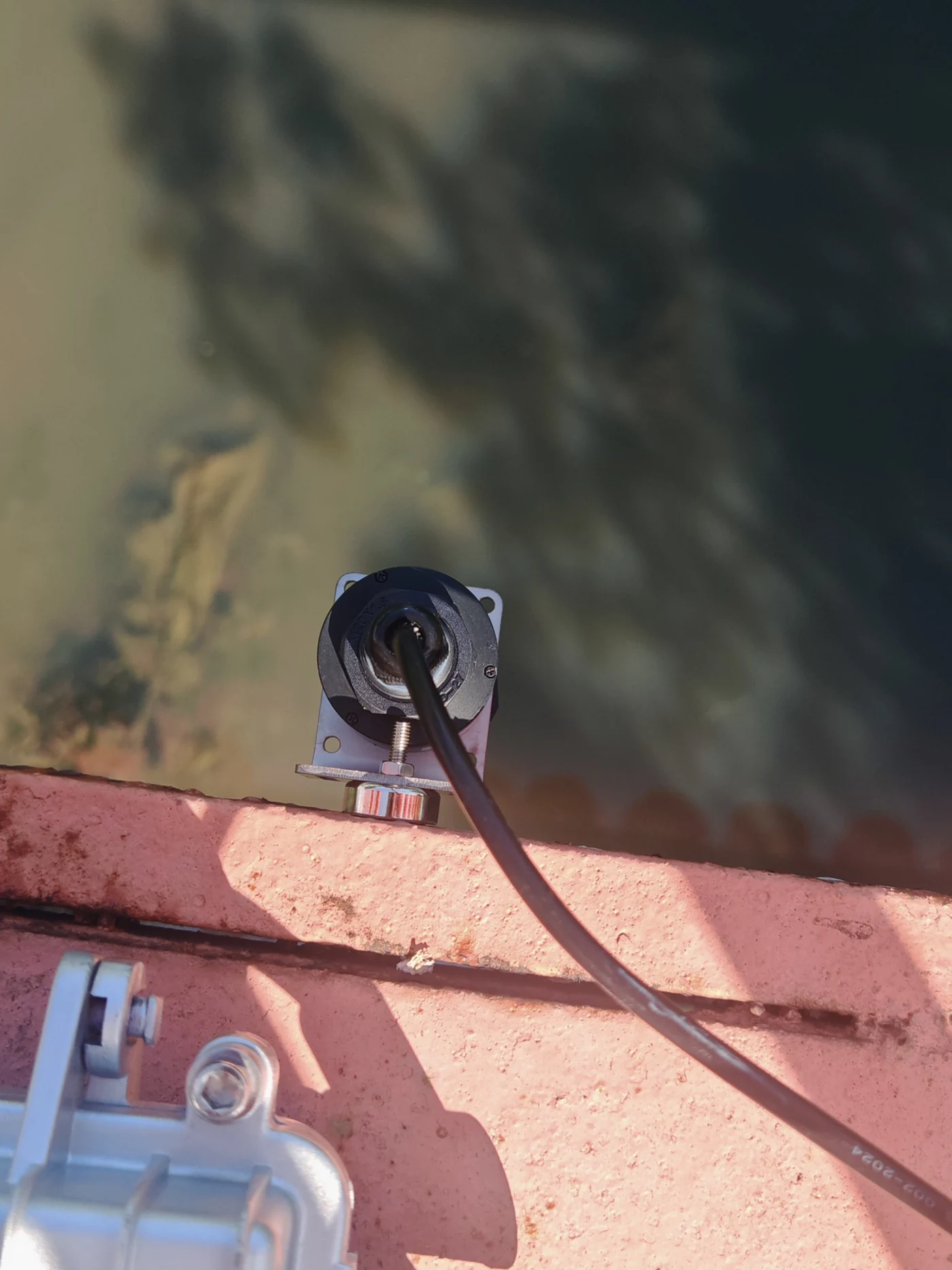
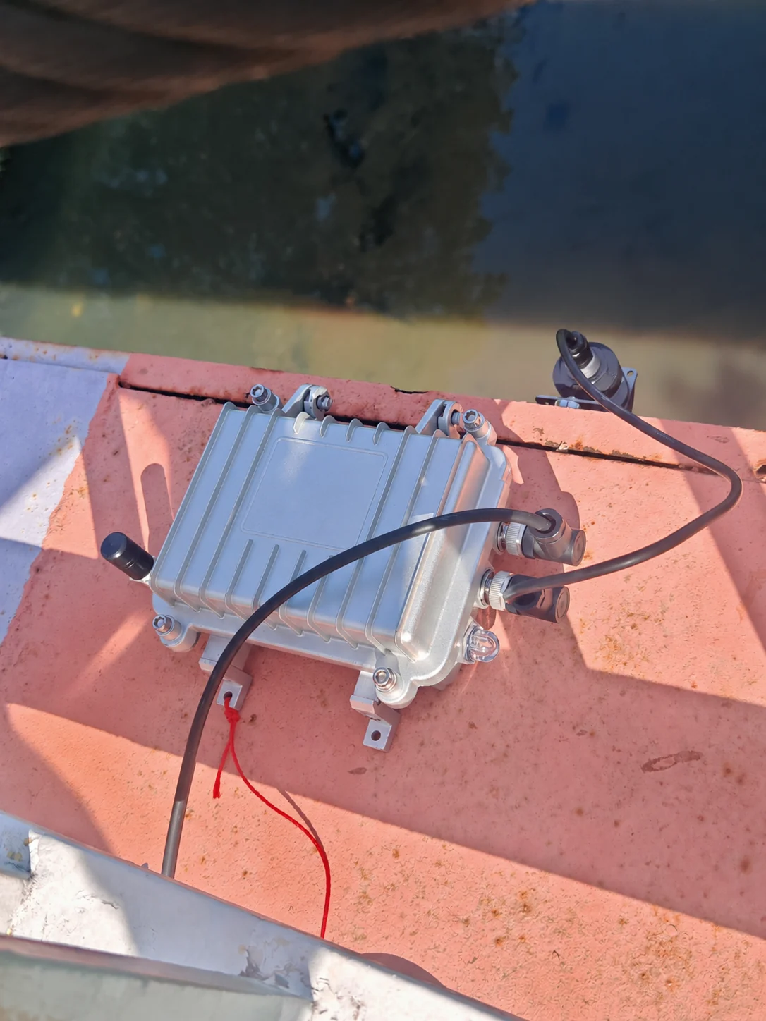
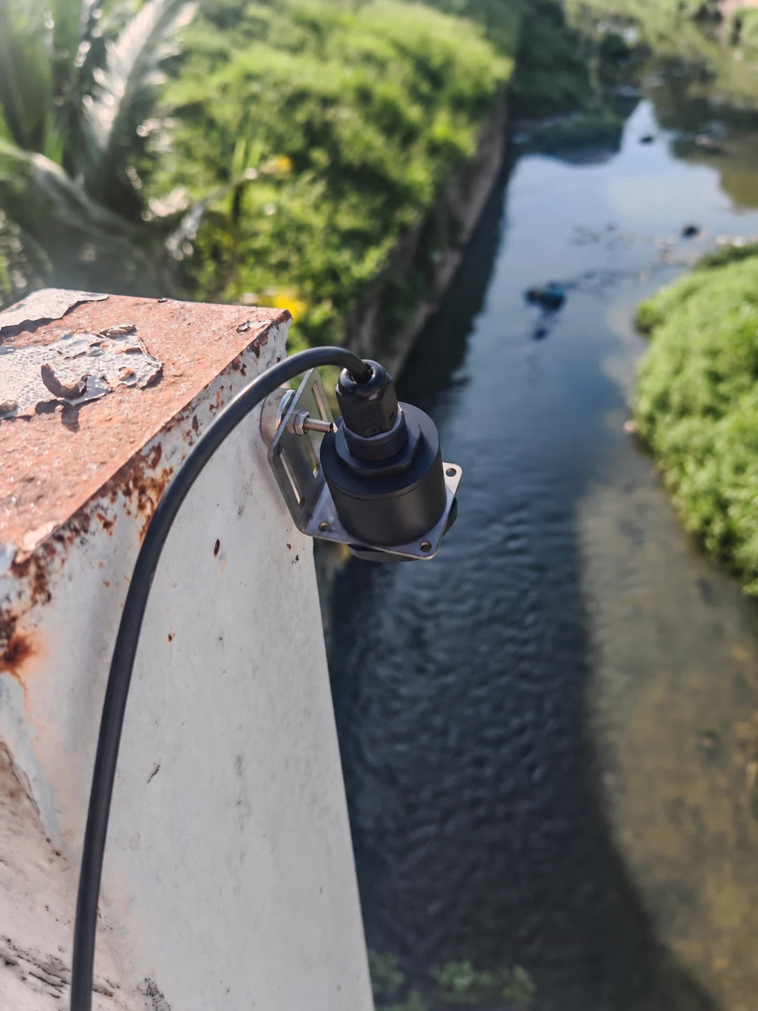
Proof of concept completed- Proof of concept completed: Supplied photographs show practical radar mounting and measurement checks.
- Sensor and station: Field images show the sensing head, bracket, cabling and monitoring hub.
- Next acceptance step: Validate measurements and alerts against site reference conditions.
Flood forecasting, warning lead time and a completed flood-response deployment are not established by this evidence.
Engineering and reliability considerations
Set the reference
Relate sensor distance to water level using the mounting height and site geometry.
Check the sensing path
Assess nearby structures and the narrow-beam mounting arrangement.
Agree thresholds
Link warning and danger levels to a specific operational action.
Verify delivery
Test measurement, history, threshold events and notification receipt.
Technical highlights
Review the documented configuration and its deployment limits.
View specifications and configuration notes
- Non-contact radar level measurement.
- Documented maximum sensing distance of 30 m and a 3° beam angle.
- Chemical- and corrosion-resistant sensor housing specification.
- Wireless mobile-network reporting.
- Replaceable 7.2 V / 19,000 mAh battery in the documented metal-series configuration.
- IP65 monitoring-station enclosure specification and documented 0–60°C operating range.
- Level-history dashboard and configured threshold notifications.
Maximum range is a sensor specification; usable site performance must be confirmed during commissioning.
Deployment process
Survey & install
Check geometry and radar mounting.
Register & baseline
Set reference, battery and signal.
Controlled test
Compare with reference conditions.
Tune & verify
Check warning levels and notifications.
Report & scale
Review pilot evidence before expansion.
Discuss Your Monitoring Requirement
Tell us the infrastructure type, measurement environment and rising-water condition you need to detect. We can propose a practical pilot configuration.
Email AI-REKA